The Schaublin 70 and 102 lathes employ a very similar range of accessories that very ofter are only distinguishable from each other by size, due to this the illustrations are of a mixture of 70 and 102 accessories. Over the years the number of accessories available have been very much reduced. Schaublin’s current accessory range is probably less than a tenth of that available in the 1950s. The catalogues from which the illustrations below are taken can be downloaded from the individual Schaublin 70 and 102 pages.
Milling attachments

SV70 B8 milling attachment

Schaublin 102 W12 milling attachment
Milling attachments consists of a vertical slide with an inclinable milling spindle. The milling attachment is designed to clamp to the lathe carriage tee slots and is driven by a 6mm round belt from overhead. These attachments are incredibly useful even when milling facilities are available since so many jobs can be turned and milled in one chucking. This is particularly useful when concentricity is paramount as in horological wheel and pinion milling. Two versions of milling attachments for the Schaublin 70 and 102 exist. The earlier attachments had flat backs while the later ones had “humped” backs and this is generally how they are known. The 70 and 102 items are very similar except in size and in the type of collet employed. Early flat back 70 milling attachments used B8 (horological) collets while the 102 version employed W12 collets and had a speed reduction gearbox fitted to the spindle.

Schaublin 102 W20 “hump-back” milling attachment
Later hump back attachments employ W12 and W20 collets for the 70 and 102 respectively. While humped back versions are obviously more rigid than the earlier attachments both are extremely sturdy and more than fit for their purpose.

SV102 milling attachment speed reduction gearbox
For the SV102, the flat back attachment has some advantages over the later “hump-back” item mainly due to its compactness and built in speed reduction gearbox. The earlier milling attachment is particularly useful for horological milling. On the other hand, the larger collet capacity and higher spindle speeds of the later attachment have distinct advantages for certain types of work. A speed reduction gearbox with a ratio of 4.5:1 was also available for the 102 hump-back attachment.

Early type Schaublin 70 milling attachment with microscope set up for “watchmaking jig boring”
The grinding attachments illustrated elsewhere can also be fitted to the vertical slide as can a microscope and high speed milling and drilling spindle (made by GEPY) enabling jig boring operations to be conducted. In the illustration to the left a Schaublin 70 has been set up with a quick-change headstock and quill with mandrel-type face plate with raised clamps ready for a typical watch-making operation. A microscope is shown in the vertical slide quill-holder for precise positioning of a cutter held in a GEPY quill which replaces the microscope. The headstock quill has a diameter of 35mm, and although Schaublin never said as much, it was designed to be compatible with the Hauser H1 “machine à pointer” and could be transferred from one machine to the other with the work still in place.
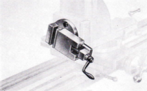
SV102 milling vice
Other accessories that could be mounted on the vertical milling slide included a T-slotted milling table, indexing head and milling vice.
Schaublin grinding spindles

SV102 ball bearing grinding attachment
Schaublin have produced a number of different types of grinding spindle for the SV70 and 102 lathes, some employing plain bearings others with ball bearings. Early grinding spindles for the SV70 employ B6 collets while B8 collets are used in both the later SV70 and SV102 devices. Plain bearing devices have a top speed of around 10,000 rpm while spindles with ball races have a top speed of around 15,000 rpm.

SV102 internal grinding attachment
An internal grinding device was also available for both the 70 and 102 with a rather low maximum spindle speed of 18000 rpm.

SV102 grinding attachment mounted on milling attachment vertical slide
Schaublin 70 and 102 Grinding Carriages
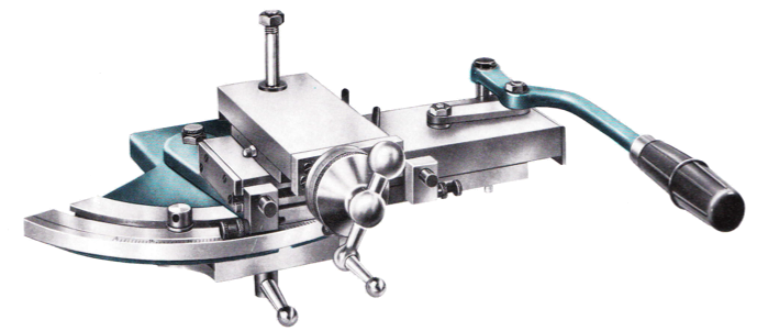 The Schaublin 70 and 102 lathes can be quickly turned into cylindrical grinding machines through the use of the grinding carriage and grinding spindle. These carriages have covered slideways to prevent ingress of grinding dust. Of course, great care must be taken to prevent grinding medium contaminating bearings and wearing the tailstock and bed etc.
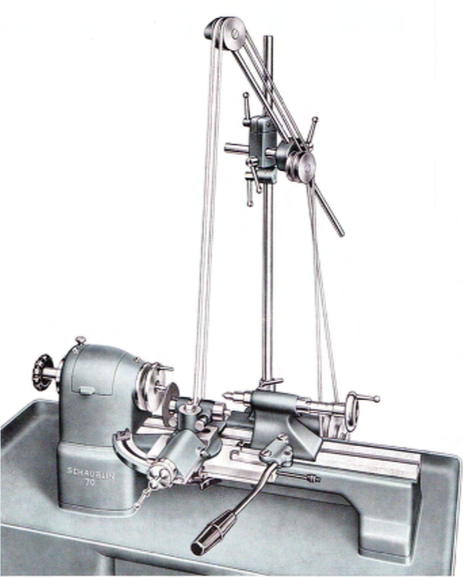
SV70 with set up with grinding carriage, plain bearing grinding spindle and overhead drive
Schaublin Overhead Drive for Milling and Grinding Attachments
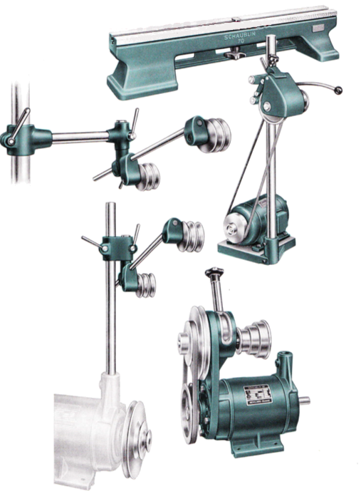 The drive for the milling and grinding attachments for the Schaublin 70 and 102 lathes is provided by a 6mm round belt supported by an array of four pulleys and driven either by a separate motor as in the illustration below, or by the headstock drive unit on bench mounted open headstock machines as shown to the left. More recently Schaublin have adopted a column mounted motor with frequency control. Schaublin also offer the option of milling and grinding spindles featuring their own integral motor units.
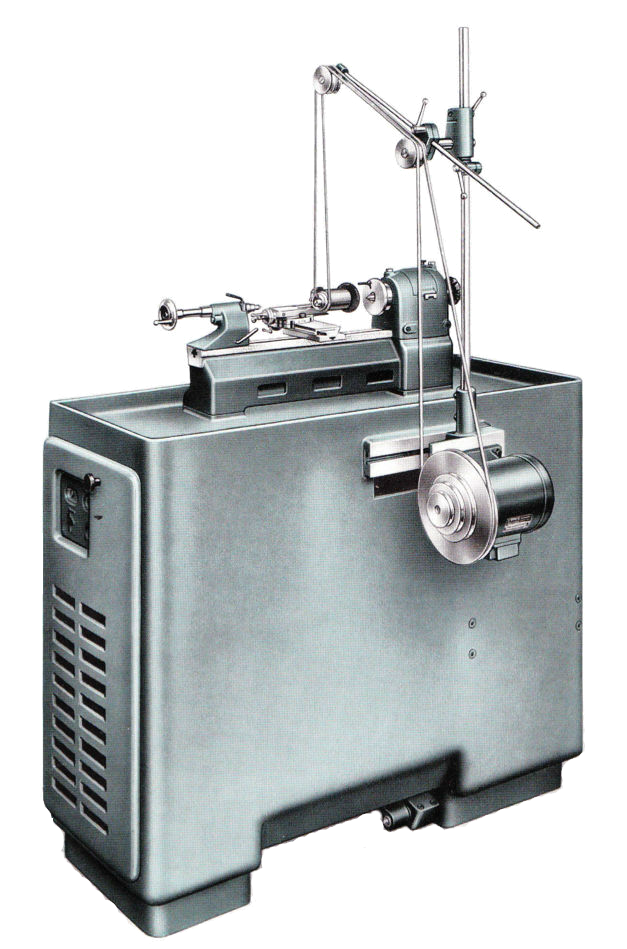
Dividing Attachments

SV102 worm and wheel dividing attachment
Headstock dividing attachments for the Schaublin 70 and 102 lathes are very rarely found on the second hand market. While these attachments are very useful they are easily substituted by direct indexing with a suitable dividing plate and detent. Indeed for many horological applications the dividing attachment is not suitable since some common horological wheel counts are unobtainable with a 1:60 ratio.
Quick Change Tool-Posts
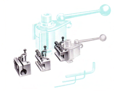
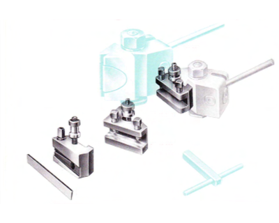 Schaublin list two types of quick change tool-posts for the 70 and 102 lathes, the (now French made) Multifix (left) and Tripan (right). Both types are excellent, the Multifix being particularly sophisticated with 40 indexing positions for the tool. However, in my opinion Tripan tool-posts are ideally suited to the 70 and 102 and being slimmer than the rather bulky Multifix unit, obscure the working area much less.
Microscopes
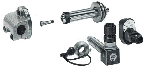
 Schaublin list Isoma microscopes for fitting to the tailstock (left) and for use in the vertical slide of the milling attachment (below – also showing quill holder and quill). These are extremely useful for the setting up and measurement of work.
Screw-cutting attachments
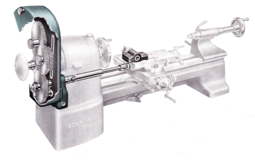 A number of screw-cutting and power feed attachments have been made for the Schaublin 70 and 102. However, like many of the specialist accessories for the 70, the screw-cutting attachment (left) was supplied in very small numbers and was eventually deleted from the accessory range in the mid 1960s. It is probably the rarest Schaublin 70 accessory on the second-hand market.
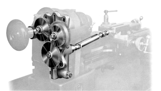 For the 102, Schaublin provided three seperate means of generating threads. The first type (right) consists of a train of gears driving directly from the headstock spindle through a telescopic shaft with a pair of universal shafts to the carriage top-slide feed-screw. The carriage top-slide feedscrew is supported by a hardened plug with a spigot which locates in the end of the feedscrew. When screw-cutting this plug is removed and replaced by the driving end of the universal shaft. No clutch in the screw-cutting drive chain is provided. The use of these attachments under power on machines without a back-geared headstock and not provided with a clutch and brake to the spindle drive must require nerves of steel!
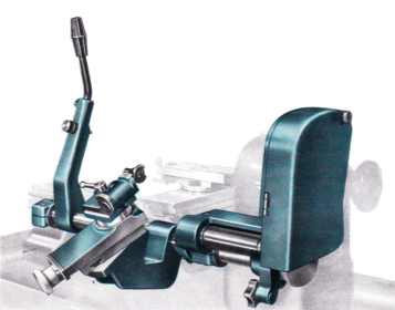
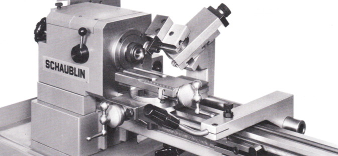 The second method (left and right) which Schaublin referred to as “screwcutting attachment with leaders and gears” but also commonly known as “hob and drag” screwcutting, used a master screw, or hob, with a follower drawing a bar with a slide and thread form tool form tool. This method of screwcutting was more suited to batch production rather than one-offs. Schaublin also produced an hob-and-drag attachment specifically designed for the F-type production headstocks.
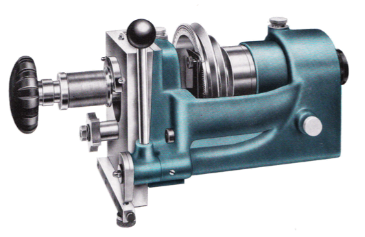 The third method of generating threads involved a special sliding spindle headstock – a one of the earliest methods of generating a thread on a lathe – in which the thread was generated by the tool remaining stationary while the spindle moved along the axis of the lathe. In this method the movement of the spindle is controlled by a master hob on the end of the spindle into which is engaged a follower which is fixed to the headstock. This screwcutting method is particularly suited to the production of short threads fine threads such as those used in optical equipment.
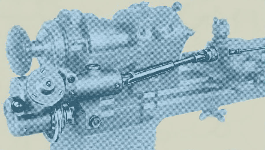
 In addition to the geared carriage screwcutting attachment, for a very short time Schaublin also produced a very sophisticated belt driven power feed attachment. Featuring a multi-plate clutch and reversing gearbox, the powerfeed was transmitted to the top-slide feedscrew via a universal shaft with quick decoupling device. A further attachment allowed the drive to be taken to the cross slide feedscrew allowing powered facing operations to be carried out. To my knowledge, these attachments only appear in the 1957 catalogue – very rare indeed.

Spherical turning carriage
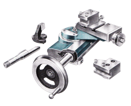 Schaublin spherical turning carriages are primarily designed to be worm and wheel controlled and operate by rotating a movable slide around a fixed central point. The attachment could produce both convex and concave work. Careful setting-up is required to ensure that the pivot point is on the lathe axis and at the correct position relative to the work. To this end Schaublin provided special setting devices. The carriage could also be converted to lever operation with the worm-wheel being used to operate a cylindrical rack acting as a stop.
Tailstocks
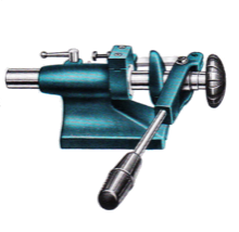 |
Tool-room machines (TO designation) where usually supplied with a screw-operated tailstock. However, the standardisation of headstock height on all machines meant that tailstocks were interchangeable with a very high degree of accuracy long after initial purchase. Schaublin offered a range of tailstocks including lever operated (left), lever and spring operated (for grinding operations) (below) and, for the 102, turret-wheel rack and pinion operated (right). The turret wheel operated tailstock was mainly intended for second-operation work. | 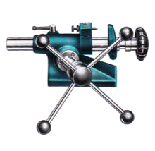 |
 |
Lever and turret wheel tailstocks took W type collets, while screw operated and lever and spring operated had a tapered socket (SV70: 2º; SV102: 2MT). In general use the standard screw operated tailstock is more than sensitive enough for the smallest of drilling operations, however there are occasions when a lever tailstock provides that extra degree of sensitivity or fast operation. Schaublin also listed a B8 colleted revolving spindle to fit the lever tailstock. Driven from the overhead drive it could be run at up to 5000 rpm.
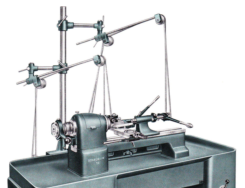
Schaublin 70 fitted with lever tailstock with B8 spindle
