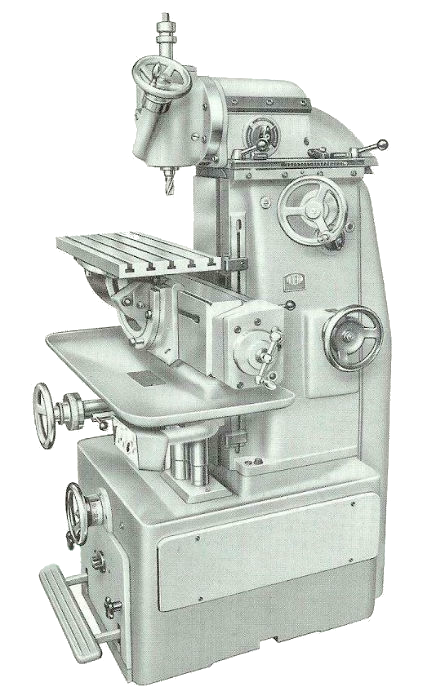
Early Aciera F4 with vertical head and universal table
While F1s and F3s were sold in quite large numbers from the 1950s to the 1990s, the F4 is much less frequently encountered. A much more sophisticated and substantial machine than the F3, it was just under three times as expensive as its smaller sibling.
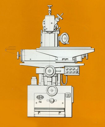
Supplementary table displacement
Weighing in at 900kg, nearly twice as much as an F3, the F4 is a very robust machine with accessories to match. Travels measured 400mm for the longitudinal (x) axis, 450mm for the vertical (z) axis and 190mm for the headstock transverse (y) axis. However, by using a precision scraped V-way on the top of the longitudinal slide, travel of the x axis could be doubled to 800mm by sliding the table or other accessories along the “apron”.
The wide range of speeds and slightly larger capacity gave the F4 a considerable commercial advantage over other Swiss-made machines such as the Schaublin 13 or Sixis 103. The combination of infinitely variable feeds and speeds which could be “tweaked” whilst undertaking machining, made the F4 extremely user-friendly. Very late F4s were also offered with an optional electrically powered self-acting feed unit for the headstock (y) axis, further enhancing the machine’s appeal.
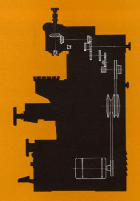
Spindle drive kinematic train
Drive to the horizontal and vertical spindle was provided by a 1.85kw single speed motor located in the machine’s base. From the motor, drive was taken via v-belt driven variator to a gearbox located in the main column giving two speed groups for the both the horizontal and vertical spindles. Another gearbox located in the horizontal headstock gave a further two speed groups for the vertical head alone. Thus, infinitely variable speeds of between 50 and 2000rpm in two groups were obtainable at the horizontal spindle while the headstock gearbox increased the top speed of the vertical head to 3400rpm.
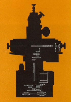
Feeds kinematic train
Located in the base of the machine and independently motor driven, the feeds gearbox featured two geared ratios coupled to a v-belt variator drive giving infinitely variable feed rates between 12 and 360 mm/minute to the longitudinal (x) and vertical (z) axes. A foot control to the front of the machine engaged rapid traverses. Each powered traverse was fitted with knock-out stops with fine adjustment.
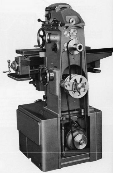
Spindle variator drive
In terms of construction the F4 consisted of a rectangular cuboid base casting housing the coolant tank, feeds gearbox, spindle motor and electrical equipment onto which was bolted the main body of the machine. The body carried the vertical (z) axis male dovetail and female dovetail for the transverse (y) axis. It also formed the main spindle gearbox oil-bath enclosure and housed the y axis feedscrew control and spindle variator control. The horizontal headstock with the two speed vertical head gearbox was of conventional construction employing NN-type double row adjustable roller bearing to the front of the ISO 30 (40 on request) spindle. The drive to the vertical head is transmitted via a splined socket and shaft rather than through the horizontal spindle socket. This arrangement is necessary since the headstock contains further gearing for the vertical head alone. Like the F3 the horizontal headstock feedscrew does not rotate, instead the ball bearing supported nut is rotated via bevel gears. The massive combination dovetail/rectangular section longitudinal (x) slideway was provided with two tapered gibs (one top, one bottom) adjusted by helical square-form screws. Hardened large diameter feedscrews for all axes were carried in ball bearings and featured ground trapezoidal threads and non-adjustable bronze nuts. The vertical head consists of a casting containing a massive sliding quill, handwheel controlled via helical rack (directly machined into the quill) and worm pinion. An optional lever feed was also offered. Precision cylindrical roller bearings carried the spindle with lubrication provided by an oil-bath within the head casting. ISO 30 spindle tooling was secured with an M12 drawbar incorporating a simple but clever tool ejecting mechanism. Power was transmitted to the spindle via a pair spiral bevel gears, an arrangement which can make these machines fairly noisy at higher speeds.
|
Accessories included all the usual augmentations to the continental pattern milling machine, such as a tilting table, rotary table, dividing heads, slotting head etc. Of particular interest are the co-ordinate rotary table and universal milling head. The latter connected to the vertical head via a bayonet type fitting and allowed the cutter to be placed in any plane relative to the work. The former, in an age before computer control, was employed in the production of complex workpieces such as punches and dies. |
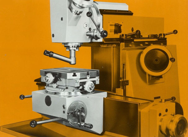 Co-ordinate table |
While the F3’s equipment and accessories were of a size and weight easily handled by a fit working-age man, much of the equipment for the F4 was of hernia inducing proportions! At 60kg, the weight of the vertical head is somewhat of a disincentive to changing from vertical to horizontal operation and many late machines were fitted with a pivoting slide arrangement to aid removal and replacement. The fixed and tilting tables at 77 and 66kg respectively, further detract from the machine’s appeal to the hobbyist who’s workshop is without mechanical handling equipment or an obliging (and well-built) neighbour! While the weight issues might be a disincentive to ownership, the comprehensive range of accessories coupled with the machine’s relatively compact footprint, good capacity and Aciera’s superb build quality nonetheless make it one of the most desirable medium sized mills on the used market.
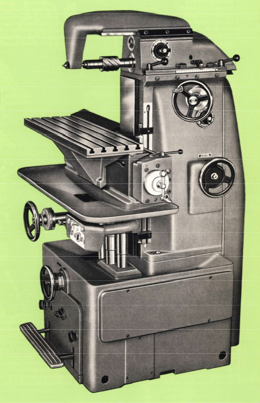
They could never be described as beautiful, but early F4s have all the attractive curves and aesthetic appeal of mechanical artifacts of the 50s and before; later squared-off machines are much less attractive, but nonetheless have a handsome brutality!

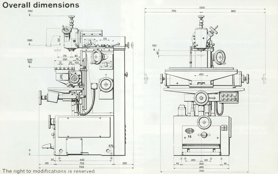
Aciera F4 overall dimensions

