
 First introduced in the 1930s, the screwcutting version of the 102 lathe gives up some of its flexibility for power feeds and screwcutting. Like the plain lathe the centre height is 102mm but admits 450mm between centres. These machines, like all Schaublin screw-cutting lathes, are not only superbly made but also very complex. In the post war period around 3750 102-VMs were produced with the final machine being made in 1975.
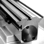
 Designated the 102-VM (Vis-Mére – literally meaning “mother-screw”), the machine featured a massive centrally positioned 40mm leadscrew running the length of the bed providing both powered-feed and screw-cutting functions. The hardened cast-iron bed itself was of equally massive proportions and consisted of a central trapezoidal section (the same dimensions as the plain 102 bed) on which the headstock and tailstock located with a front raised V and rear flat to guide the sliding carriage. A pair of steel covers protected the ways from swarf and foreign matter.
The back-geared headstock was available in either W20 or W25 execution and followed the same basic design as the plain 102. The same was true of the tailstock with the exception that for the VM a facility was provided for off-setting the tailstock for taper-turning operations. Like the plain 102, two types of tailstock were made. Prior to 1964 machines had a tailstock barrel to which the cast-iron traversing handle was attached. These earlier machines employed Schaublin’s own 2º taper socket. Later machines used the “magic-eye” style tailstock used on the 70 and 102. These later tailstocks have 2 morse taper sockets.
 Following the contours of the central trapezoidal section without contacting it, the carriage formed an elegant bridge spanning the bed from the front V to the rear flat. The cleverly designed bed/carriage combination allowed the carriage to have long bearing surfaces which did not impede its travel in respect of the headstock or interfere with the positioning of the tailstock. The cross-slide had a fixed nut while the feedscrew and handle remained stationary. So as not to interfere with the positioning of the compound slide, the large cross-slide feed-screw handle and micrometer dial were positioned lower than the axis of the feedscrew with a zero backlash pair of gears transmitting motion from one to the other. Powered cross-feed was not provided. The compound slide was of the same design and proportions as the plain 102 top-slide with the exception that it had a “two-pronged” ball handle.
The carriage apron carried the hand-wheel for manual traverse of the carriage by rack and pinion as well as three other controls: two associated with engaging and disengaging the feed-screw nut (see below); and one for controlling the rotation of the feed-screw via and reversing gearbox and single-dog clutch. The latter was contained within the complex gearbox slung on the headstock end of the bed (see below).
A single 120mm long bronze nut engaged with a third of the circumference of the feedscrew in order to transmit feeds and screw-cutting functions to the carriage. The nut was engaged by a lever on the front of the apron lifting and latching a substantial arm (to which the nut was attached) slung under the bed and pivoted on the rear of the carriage. This arm also cleverly formed an oil reservoir providing lubrication to the nut.

 While the movement of the carriage for both screw-cutting and feed functions were delivered by the lead-screw and nut, two different methods for rotating the lead-screw were furnished by the machine’s gearbox. For the generation of screw-pitches the lead-screw was driven from the headstock spindle via a single ratio gearbox and change-wheels. For feeds, on the other hand, the lead-screw was driven from the headstock spindle via a V-belt and pulley system located behind the headstock. The latter employed a worm and wheel to take power from the headstock to the driving pulley. This is a vulnerable part of the design and if not properly engaged or adequately lubricated can suffer from extensive wear and damage. The use of belts to drive the feed-screw not only reduces noise, but allows much quicker selection of feed-rates via the four stepped pulley set. The pulley set was also reversible giving a further four feed rates.
Whether in screw-cutting or feeds mode, the lead-screw’s engagement and direction of rotation is controlled by a single-dog clutch and reversing gear-set contained withing the gearbox. This is actuated via a lever on the apron with three positions: forward, neutral and reverse. The use of a single-dog clutch allows for screw-cutting without disengagement of the lead-screw nut, which means a thread can be picked up in the same place by the tool every time. It is somewhat curious as to why Schaublin did not incorporate knock-out stops to actuate this mechanism in the way Hardinge and others did with their machines. Knock-out stops are provided, but these act on the latching mechanism for the lead-screw nut rather than the dog clutch mechanism which means once the lead-screw nut is disengaged a thread cannot be picked up with any certainty.
 Machines built prior to 1954 were mounted on fabricated steel cabinets with cast iron chip trays connecting the two pedestals of the stand together. Later cabinets were, like the plain 102, a single piece casting. The left hand pedestal contained the machines motor and counter-shaft unit. A number of drive configurations were offered from manual flat belt shifting to V-belt variator drive (identifiable by a large hand-wheel on the left hand pedestal). Machines were fitted with three phase single voltage two speed motors which in combination with the counter-shaft arrangement and headstock back-gearing gave a wide range of speeds. Additionally, machines could also be fitted with a foot operated clutch and brake counter-shaft allowing extra convenience and safety. Whether on a fabricated or cast-iron stand the 102-VM was a heavy machine weighing in at 500-600kg.
 In terms of accessories most of those for the plain 102 were compatible with the 102-VM. Obvious exceptions were the carriages, but milling attachments and grinding spindles were equipment common to both machines. One notable compatibility exception was the the dividing attachment, which for the 102-VM was significantly different to that for the plain 102 – a very rare and desirable accessory.

Schaublin 102N-VM
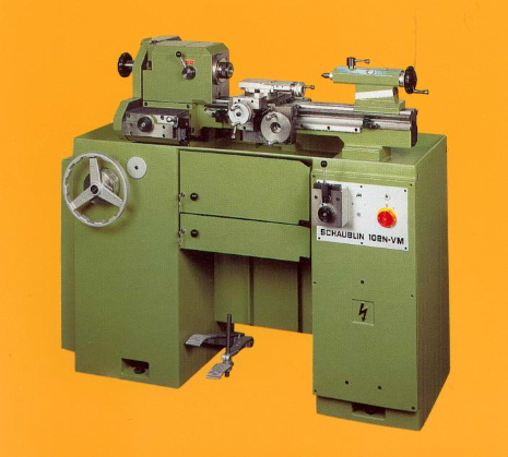
 The mid ’70s saw a complete redesign of the 102-VM and, as with other models in the Schaublin range, the machines attractive curves gave way to angular brutality. The 102N-VM (N for nouveau = new) was a complete departure from the earlier machine and, in my opinion, not entirely for the better. The only features that remained the same were the trapezoidal part of the bed and the position of the lead-screw. The bed now had dovetail ways for the carriage and the new design compromised the travel of the carriage since its movement was impeded by the headstock.
  While the lead-screw remained in the same position the method of nut engagement changed to a clasp-type arrangement (photo left – feed-screw and apron viewed from below). Like the earlier machine knock-out stops were provided to disengage the nut while in power-feed mode, but no single-dog clutch was included in the new design. Instead a lever located to the right of the feeds gearbox (photo bottom left) connected to a tumbler reverse mechanism simply engaged and disengaged the mesh of the gears to the feed-screw. This could be executed while the machine was running with “crashing” only becoming a real problem at high speeds with high rates of feed – under such circumstances disengagement of the lead-screw nut was a safer approach. The tumbler mechanism also incorporated an adjustable overload device that would un-mesh the gears if the pressure on the feed-train became too great.
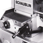 One great improvement on the 102-VM offered by the new model was the provision of a feeds gearbox (right). This neat unit mounted below the headstock on the front of the bed was belt driven from the spindle and featured a single knurled adjustment knob giving eight rates of feed from 0.02 – 0.3 mm per revolution of the spindle. The rate of feed could be adjusted while the machine was running and in-feed and represented a huge gain in convenience compared with the earlier machine.
 For screw-cutting operations the feeds gearbox was disconnected and a conventional change-wheel system used. However, the lead-screw was still connected to the change-wheels through the tumbler mechanism and the omission of a single-dog clutch meant that during screw-cutting operations the headstock to lead-screw transmission train could not be disengaged. Instead the machine’s clutch and brake (where fitted) were used, coupled with a quick withdrawal of the tool and then the motor reversed to return the carriage to the beginning of the thread.
 While the 102-VM was only available with a back-geared headstock this was optional on the N-VM. The 102N-VM was also offered with a wide variety of drive and mounting options. Most notably, as well as being available on a cast-iron cabinet, it was available as a bench mounted machine with either rear or under drive unit. Presumably this adaptability was adopted in order to widen the machine’s market and allow greater pricing flexibility. However, without the clutch and brake – only available on the cabinet mounted machines – screw-cutting must have been extremely nerve-wracking – especially so on machines without back-geared headstocks.

Over a number of years I have owned and extensively used both the 102-VM and the 102N-VM, and I would have to say that my preference would be for the former. The 102N-VM is a very nice machine and the feeds-gearbox is an extremely convenient addition, however by comparison, it is somewhat clumsy and less refined than the curvaceous 102-VM.