

Schaublin 135 circa 1970
The 135, 150 and 160 were the largest of the manual lathes produced by Schaublin. While small when contrasted with the output of firms such as Oerlikon or the UK’s Dean, Smith and Grace, in comparison to Schaublin’s other lathes they are leviathans – the 160 weighed in at 1800kgs!
Built to an uncompromising standard these machines were beautifully constructed, both mechanically and electrically complex and consequently very expensive. They have a reputation for great longevity and, if cared for, can be astonishingly accurate even after many years of service. However, machines do wear, especially if abused. The reconditioning of such a machine is a major and very expensive undertaking and will probably entail more expense than purchasing a good machine in the first place.
While all three machines followed the same basic design pattern, only the 135 and 150 are identical in every respect except centre height and distance between centres – 630mm for the 135 and 600mm for the 150. Consequently the first part of this article will deal with the 135 and 150 together (and with the 160 where applicable). The 160 will receive individual attention at the end of this article.
schaublin 135 & 150
The Schaublin 135 and 150 models represent two forms of the same machine with the 135 being produced between 1965 and 1975, and the 150 between 1975 and 1998 with an overlap in production of just a few months. Around 1500 135s were built and just over 2100 of the 150s.
 The 135 and 150 were built around a massive and generously webbed bed with a section 270mm wide by 320mm deep. The design of the bed allowed a larger swing over the bed than might be predicted – 315mm for the 135 and 340mm for the 150. With hardened and ground shears formed of two prismatic and two flat ways, the bed was spanned by conventional looking carriage with double walled apron. However, rather than having the carriage traversed by an acme type feedscrew and/or rack and pinion, a high precision recirculating-ball lead-screw, tucked up under the front shear of the bed and further protected by “Elasticone” helical spring covers was used. During screw-cutting and sliding feeds, this ball-screw remained stationary while the ball-nut contained in the apron was made to rotate about it. A splined shaft located below the ball-screw transmitted power to the apron from the machines’
 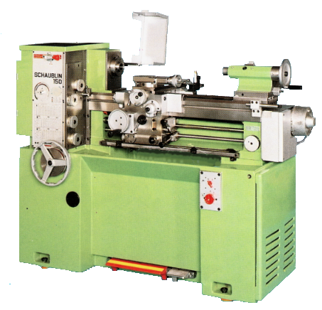 substantial feeds and screw-cutting gearbox located in front of the headstock. The manual traverse of the carriage was achieved via an unusually large (200mm) hand-wheel – necessary since one turn would only advance the carriage by 15mm. On later 135 models the option of a rapid longitudinal traverse was offered where an electric motor operated by a lever on the left of the apron rotated the ball-screw. Machines fitted with rapids are identifiable by their much smaller carriage hand-wheel and a motor and gearbox housing on the right-hand end of the bed. Rapids were standard equipment on the 150 model.
 The carriage located on the front V and back flat of the bed over a length of 400mm, while tapered gibs captured the carriage on the undersides of the front and back ways. The double walled oil-bath apron carried a hand operated oil pump for the bed ways and cross-slide, movement-locks for both axes and a single four position lever for controlling sliding and surfacing feeds in both directions. A neat two direction stop-device was incorporated into the cross-slide feed-screw mechanism which allowed quick retraction of the cross-slide during screwcutting operations. The main motor low/high speed, forward and reverse control lever was located on the right of the apron and operated a shaft acting upon the electrical equipment contained in the right-hand end of the cabinet. A clever disc mounted on the end of the bed allowed the selection of combinations of low speed, high speed, forward and reverse, preventing unintended selection of speed and direction whilst carrying-out critical machining operations such as screwcutting.
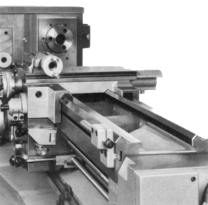
Automatic stops during surfacing feeds were achieved through the use of an adjustable clutch in the apron’s gear-train which would trip when the carriage’s travel was impeded. The stop in the headstock direction of travel consisted of a turret type device located on the left-hand side of the carriage and a neat retractable cylinder with a rack cut into it housed in the gearbox casting. The cylinder had a conventional ball handle on its end which when partially rotated disengaged the rack and allowed the cylinder to be withdrawn and then locked in a new position. The turret stop provided fine adjustment. In the opposite direction a simple adjustable stop-bar impeded the movement of the carriage.
A bar on the bed set just below the apron carried a pair of stops to automatically operate the motor control lever. This was principally designed for use during screw-cutting operations where the spindle and carriage would be rapidly and accurately arrested whilst the tool was withdrawn by the operator aided by the use of the aforementioned cross-slide stops. This method might sound a little terrifying, but in practice, while not as slick as the use of a single-dog clutch, works remarkably well largely thanks to the machine’s extremely effective brake.
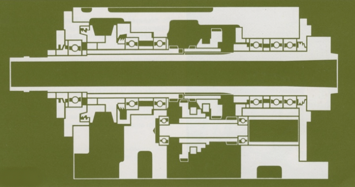
Later-type headstock AC bearing arrangement
The headstock mirrored the rest of the machine’s proportions and sophistication. The spindle on all the large machines had a cam-lock D1-4″ nose and a 5MT internal taper. All would pass 40mm through the spindle and were supplied with a B32 collet adapter and draw-bar. Earlier 135s had double row SKF NN-type bearings with micro-adjustable radial clearance fitted to each end of the spindle and a pair of special pre-loaded angular contact bearings for thrust. Later 135s and the 150s had no less than four precision angular contact bearings, three at the front and one at the rear to carry the spindle. The headstock drive pulley was carried on a pair of AC bearings of its own which not only isolated the spindle from forces applied to the belt, but facilitated the use of 1:4 reduction gearing, the selection of which was electrically locked to prevent engagement whilst running. Headstock bearings were continuously lubricated by an electric pump and reservoir located in the machine’s one-piece cast-iron cabinet. A tell-tale on the top of the headstock, consisting of a ball rotating under an acrylic dome, assured the operator that adequate lubrication was reaching the headstock bearings. In addition, the same lubrication system constantly bathed the feeds and screw-cutting gearbox as well as lubricating the spindle speed variator.
Located in front of the headstock the 135/150s feed and screw-cutting gearbox featured the quick selection of 24 feeds and total of 110 metric, imperial and modular thread pitches when used in combination with change-wheels. When feed mode was selected the gearbox was belt driven from the spindle, while in screwcutting mode, of course, a gear connected the spindle and gearbox. The selection of feeds was via disc-type knobs located on the face adjacent to the bed and could be shifted whilst the machine was working. When in screw-cutting mode the same knobs together with a combination of change-wheels selected the pitch to be cut.
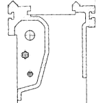
The tailstock of the 135, 150 and 160 models located on the inner flat and V of the bed. A complex and substantial unit, it was adjustable laterally and for height and could also be displaced laterally in order to allow taper turning between centres.  The hardened, ground and super-finished 50mm diameter barrel accepted 3MT tooling and featured a tang-socket to prevent tool rotation. An even more massive two-speed star-wheel type tailstock with a gargantuan 5 morse taper socket was also available.
The one-piece cast-iron cabinets upon which the 135/150 and 160 lathes stood, not only provided a suitable foundation for the lathe bed etc, but also housed the electrical equipment, lubrication pump and reservoir, cutting fluid system and chip-tray.  The early 135 had a slightly different cabinet to the later machines and the 150, but substantially there is very little difference. It has been said in a well known and extremely useful machine tool web-archive that the chip-tray is too small. Having owned a 135 for many years I have no idea to what this writer was referring. The 135/150 and 160 machines have extremely deep and more than adequately proportioned chip-trays and I have never heard any other Schaublin lathe user complain of this issue.
Depending on the model, the cabinet also housed a 3 – 4.5kw motor with an extremely effective integral brake. The simple but very effective Reeves-type speed variator mechanism consisted of a pair of wide V-belts – one from the motor, the other from the headstock spindle – coupled to a pair of expanding and contracting pulleys running on a centrally located shaft. The position of the expanding pulley shaft could be moved vertically causing the pulleys to expand or contract in opposition to each other and the belts to ride higher or lower in the V thus effecting a change in ratio.
The videos below demonstrate most of the important features of the 135 and 150.
schaublin 160

Schaublin 160 circa 1966
A total of just 200 Schaublin 160s were produced between 1962 and 1973, making it one of the rarest machines on the used market. Given that it was produced prior to the 135, the 160 was the template for its smaller siblings rather than the other way around. In general design and operational terms the 135 and 150 are extremely similar to the 160. However, the 160 differs in a number respects to its smaller siblings. 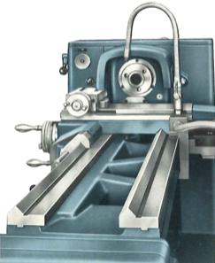
One of the most significant differences is the construction of the bed. At first glance, the beds appear to be identical, however the 160 employed separate hardened (60-62 Rc) and ground steel ways set into a cast-iron bed – similar to the American Pacemaker lathes of the 1940s. At 320mm wide, the bed was also significantly larger than that of the 135 and 150 machines.
The carriage was more-or-less the same as those on the 135 and 150 but featured a compound and cross slide made of hardened and tempered steel rather than cast-iron. The cross-slide screw had two adjustable micrometer dials geared together, one reading in whole millimeters the other in hundredths. Power feed selection through the four position lever on the top right of the apron was identical to those of the smaller machines. However, the lever below it was not for motor control (as on the 135 and 150) but for rapid feeds. The stops located on the bar below the apron limited the travels of the rapids in either direction. However, when in screw-cutting mode the rapids were disabled and the stops acted in the same way as on the 135 and 150. The bearing length of the carriage was a massive 450mm.
Later machines, as shown above, featured an electrical control box mounted on the front face of the gearbox. A number of illuminated push buttons controlled the main motor, coolant pump etc, and also the spindle speed variator which was motorised somewhat like on a Hardinge HLV-H.
When the 160 was launched in 1962 it had an opulent, no expense spared specification with its use of hardened steel for the bed-ways, compound and cross slides, and also the use of a recirculating-ball lead-screw. However, it was a fantastically complex machine and must have been astronomically expensive. In any case, it obviously did not sell well with the slightly more modestly specified 135 outstripping 160 sales nearly eight-fold. I would be very interested to hear from anyone who has experience of using a Schaublin 160.