Schaublin 65 and 70 bed clamping system.
 The history of the Schaublin 70 goes back to Charles Schäublin’s (actually named as Schaublin-Villeneuve on the original document) 1919 patent (No 81805) for the bed clamping system still used on the Schaublin 70 today. Rather than using the Webster Whitcomb or WW bed shape (as later used on the Schaublin 90 and 102), Schaublin devised his own square edged bed with headstock, tailstock and carriage sitting on a flat surface and registering on the front face of the bed. Schaublin’s 1919 patent related to the clever clamping system for the headstock and tailstock. Rather than employing a conventional T-slot running through the middle of the bed (c), Schaublin used a T-slot with one face angled at 30º from vertical (d1). A specially shaped and floating “tenon” (j) operated by and eccentric “cam” (f) simultaneously clamped the machine element (a – headstock, tailstock etc) to the top surface of the bed and pushed it toward the rear of the bed causing the front register of the element (l) to contact the front edge of the bed. The headstock was provided with two such clamps while the tailstock had one central clamp. This arrangement was first employed on the Schaublin 65 and then on the 70. The carriage (sliderest) was held to the bed with a conventional through bolt and clamping handwheel below the bed.

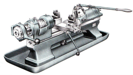
SV65 from the 1943 catalogue
In design and construction terms the Schaublin 65 and 70 were virtually identical. The major difference between the two machines, apart from the centre height and distance between centres (65/210 and 70/275 respectively) was the use of a round drive belt and W10 collets on the 65 and a flat drive belt and W12 collets on the 70. Headstocks, tailstocks and beds were specific to each model but the carriages were common to both machines. Along with the SV70, the SV65 used Schaublin’s own 2º tailstock taper (see below). Like the SV70 the 65 was supplied in both tool-room, second-operation and turret lathe forms. A push-to-close F-type collet was used on the turret lathe and some versions of the second-operation machines. These machines are generally unsuitable for tool-room / horological use.
Schaublin 70 is still made today, but the SV65 was discontinued in the early 1950s, and while a number of owners still enthusiastically use them to produce very fine work, lack of spare parts, and the relative rarity of the W10 collet makes the Schaublin 65 a poor relation to the SV70.
In horological circles the Schaublin 70 is highly sought after. As with the 65 it was available as a tool-room lathe (70-TO), second operation machine with lever carriage and tailstock (70-TL), and turret lathe (70-TR).
 Schaublin 70-TL second operation lathe |
 Schaublin 70-TR turret lathe |
 Early-type bench mounted SV70-TO from the 1943 catalogue 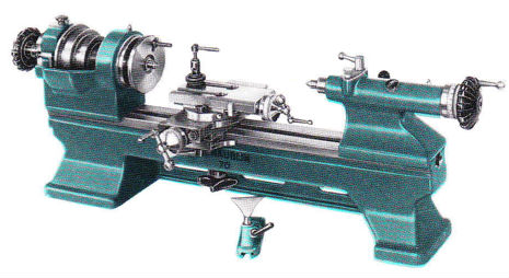 Late-type SV70-TO from the 1971 catalogue |
All machines feature a centre height of 70mm with a distance between centres varying between 210mm and 315mm. The tool-room version (70-TO) is the machine required by the horologist or instrument maker since it employs draw back W12 collets and has a screw operated carriage and tailstock (this employs Schaublin’s own 2 degree taper). The other two versions of the lathe are production machines and more than often employ an F type push to close collet system which isn’t really suitable for tool-room type work. However, the lever tailstock is a particularly useful addition to the TO machine.
Two distinct eras of the Schaublin 70 can be identified. The first is contemporaneous with the production of the Schaublin 65 and ends at the beginning of the 1960s. The second era extends from the 1960s to the present day and is the most highly developed form of the machine. The later era machines featured roller or ball bearing headstocks, all-over ground finish carriages and “window” type tailstocks. The principle differences in between the early and late era machines can be summarised as follows: |

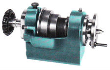
Early plain bearing headstock
Headstocks: The “anti-friction” roller bearing headstock was actually introduced in the very late 1940s. Previously all headstocks had been of the plain bearing type with a double angle front bearing of 3º (taking radial load) and 45º (for thrust) and an adjustable cylindrical bearing at the rear. This design persisted until the early 1960s when plain bearing headstocks were redesigned with a needle roller bearing taking care of thrust loads. Plain bearing headstocks can be recognised by the presence of oil cups with knurled caps.
Later “anti-friction” roller bearing design
The anti-friction bearing headstock featured an adjustable double row roller bearing (NN3006-K-SP) in the front and a pair of ball races at the rear handling thrust loads. Initially deep groove bearings were used in the rear, but these were later replaced with angular contact (AC) type. Both types of bearing are equal to the task, although the AC type are generally regarded as more suitable. These headstocks are lubricated by oil gun and have an oil nipple at each end. Grease must never be used with this bearing arrangement and oil should be administered sparingly. Over-oiling can cause overheating and premature wear.

Angular-contact bearing headstock
In the late 1970s Schaublin redesigned the headstock bearing arrangement once more and fitted a single angular contact bearing at each end of the spindle. This rather unconventional arrangement probably represents the best headstock in terms of reliability and ease of use. Bearings were greased and sealed only requiring maintenance after many years of service. AC bearing headstocks are recognisable by the absence of oil cups or oil nipples. This design of headstock is used in current machines.

Early-type carriage
Carriages: Up to the early 1960s Schaublin 70 carriages with the exception of their working surfaces were painted. Covered slides had machined and hand-scraped ways with parallel gibs adjusted with multiple grub screws. The top slide could set to any angle to the axis of the lathe against a graduated scale. Hardened and ground V form feedscews featured a cast iron nut for the top-slide and a pair of cross drilled bronze discs nuts on the bottom slide. Nuts were carefully matched to feedscrews and typically had less than 0.01mm of backlash. Feedscrews were supported in plain cast iron pillow blocks with thrust taken by a hardened disc integral to the feedscrews with an adjustable bronze disc threaded into the pillow block. Covered oil-holes were provided on the pillow blocks for the lubrication of feedscrew bearings. These earlier slides would have been silky smooth when first made, but half a century-on most will have significant wear and the options for reconditioning are limited as no replacement parts are available. Regrinding the ways can restore the original geometric accuracy, but feedscrew wear in the feedscrews and the pillow block bearings is very difficult to restore to the original fit and finish. Consequently rebuilt slides are always slightly disappointing.

Late-type carriage
Late carriages are recognisable by their all-over ground finish and engraved ruler scale to the topslide. Slide-ways had taper gibs and were pressure lubricated via oil nipples. Hardened and ground V-form feedscrews were matched with cast iron nuts (>0.01mm backlash when new). Feedscrews were supported in adjustable ball race pillow blocks and featured large satin chrome micrometer dials. A particularly clever feature of this later carriage was a patented device for resetting the topslide to zero after it had been used for taper turning. The device is very simple and once adjusted parallel with the machine’s axis is surprisingly accurate in its repeatability. These late slides are easily rebuilt to original factory specification since all components are still made.

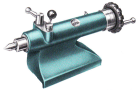
Early-type tailstock
Tailstocks: Prior to 1964 Schaublin 70 screw tailstocks had barrels which traveled through the tailstock casting. The feedscrew pillow-block and cast iron disc handwheel was mounted to the end of the barrel and traveled with it. With this arrangement the rear half of the barrel is slotted to accommodate the feedscrew nut which is fixed to the tailstock body. Barrels were hardened and ground and provided with an engraved ruler scale. The tailstock socket taper was Schaublin’s own 2º design and featured an automatic ejector. There is a difference between the dimensions of earlier and later tailstock socket tapers, with earlier versions sharing the smaller SV65 taper. Consequently, later tailstock tooling will not fit earlier tailstocks.
Late, “window” or “magic eye”, type tailstock
In 1964 Schaublin introduced the “window” or “magic-eye” tailstock, so called as they featured a perspex window in the body casting through with the graduated scale could be read. These later tailstocks are superbly made with the surface finish of the barrel and fit into the body being exemplary. The large diameter feedscrew was supported in a plain bush with a ball thrust race. A plastic handwheel of the same form as the headstock draw-bar handle, carried a satin-chrome micrometer dial reading to 0.01mm. Lubrication was provided by oil pump via an oil nipple. A barrel locking lever and, on earlier versions, a centre lubricant-well and applicator was provided at the front end of the body. These tailstocks are very hard to find on the second-hand market and command very high prices.
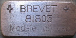 Beds: The bench mounted bed of the Schaublin 70 has remained almost completely unchanged during the entire production period. Those changes that have occurred have mainly been cosmetic. Prior to the end of WW2 all beds had the text “CH. SCHAUBLIN-VILLENEUVE BEVILARD (SUISSE)” relief cast into the centre/front of the bed. After 1946 this text changed to “SCHAUBLIN SA BEVILARD (SUISSE)” and in the early 50s it was changed again to just “SCHAUBLIN 70”. On earlier beds a small flat area at the right hand end was engraved with the words “+ BREVET + 81805 Modèle dépose” – Swiss patent 81805 registered design.
In the early 1970s Schaublin abandoned the hand-scraping of beds and they were left with a cup-wheel ground finish. Since the introduction of slideway grinding the hand-scraping of plain lathe beds was, in terms of precision, unnecessary, but was probably done in order to “add value” by giving the machines a more hand-finished look.

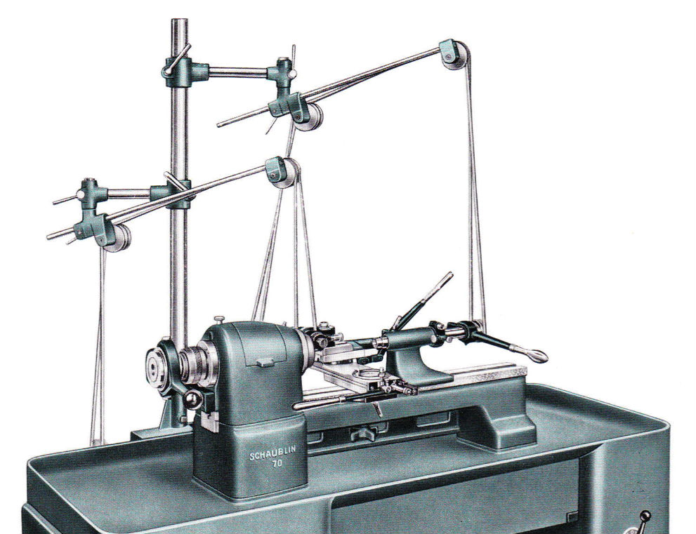
Bench bed and drive systems including “belt tensioning” attachments
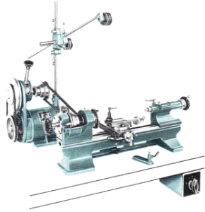 Drive System: A number of different drive systems have been available for the Schaublin 70. Before the war the 70 was only available for bench mounting, but post war a number of different options for driving and mounting the machine were available. Two types of bench drive were available: an earlier overhead type drive that was discontinued in the early 60s and an integrated motor/countershaft drive that could either be mounted behind or below the machine. A cabinet stand was also available from the 1950s onwards.

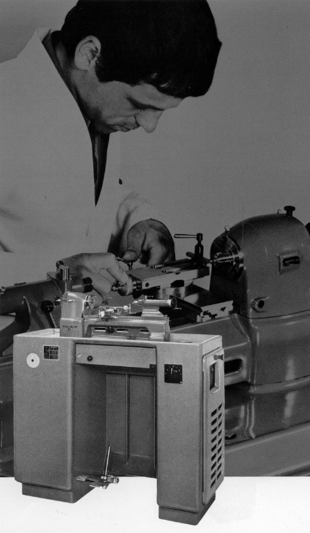
Fabricated cabinet stand
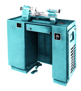 The first cabinet stands consisted of a cast iron top tray and a pair of fabricated steel pedestals, the left hand one containing the motor and countershaft. From the early 60s cabinets consisted of a one-piece casting weighing 270kg! Beds and headstocks for the cabinet mounted or under-driven bench mounted machines were different from rear driven bench mounted machines. The cabinet stand mounted 70 was discontinued by Schaublin in 2010.
The tool-room version of the Schaublin 70 from any era is an extremely versatile machine. With an enormous variety of accessories available, the Schaublin 70 can easily be turned into a small sensitive jig-boring and milling machine, wheel and pinion cutter or cylindrical grinder. Both the Schaublin 65 and 70 were built to master gauges to allow interchangeability of headstock and tailstock components. Schaublin claimed a machine could have equipment added to it over time without any adjustment of the new components being necessary. In fact, this is only partially true, since while headstocks and tailstocks were seperately adjusted to master gauges, individual machines had a further stage of matching applied to them. Nonetheless, the degree of interchangeability is very impressive. A machine recently constructed from an unused headstock and newly made tailstock was just 0.006mm outside of the original factory specification. Accessories made at any point during the entire production run of the Schaublin 70 should be compatible with a machine from any era. Bench mounted machines are in particularly high demand due to their relative lightness making them ideal as a “spare bedroom” machine for horologists. This fact often means that cabinet machines can be bought for (relative) “bargain” prices. However, both bench and cabinet mounted machines are becoming increasingly difficult to come by and command high prices on the second hand market especially when well equipped.
The video below shows a Schaublin 70 being used to cut watch wheels in the workshops of watchmaker Roger W Smith in the Isle of Man. The machine is the late-type with angular-contact bearing headstock and is fitted with a 70-87.300/450 “hump-back” milling attachment and 70-21.800 headstock dividing attachment. A superb illustration of the use of a Schaublin 70 for a non-turning horological application. The Schaublin 70 is perfect for this type and size of work. For larger horological work, such a that encountered in general clock restoration, we recommend the Schaublin 102 which is suitable for all types of horological work from carriage clocks to long-cases. It should also be noted that the very eminent watch-maker Derek Pratt preferred the Schaublin 102 to the Schaublin 70.